【Blender 2.92】Modeling a Badminton Racket
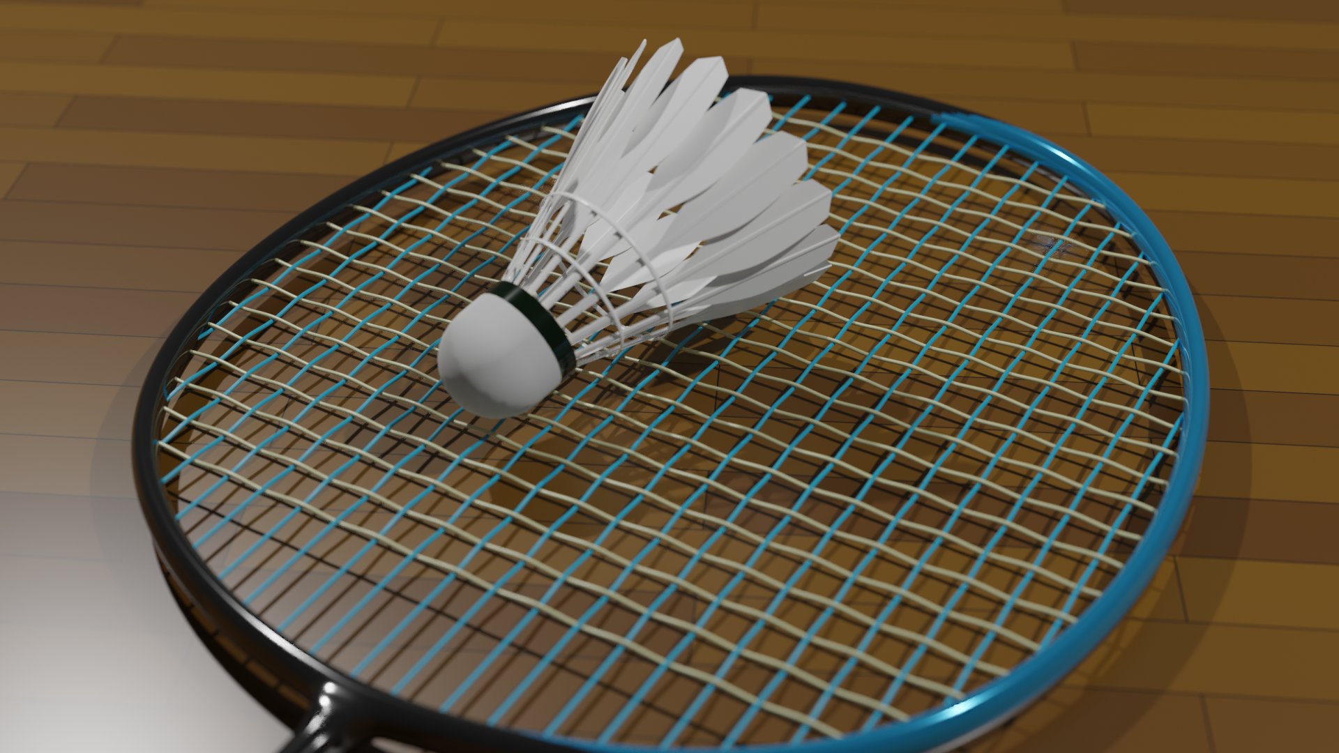
This is the explanation of the “Badminton Racket" I created on April 3.
I was inspired by Sasara Bch’s tutorial video on “Net (Mesh)" and created it 🏸
While making it by looking at the actual racket, I was a bit surprised by how realistically it turned out 👀‼️ Haha.
I’ve summarized the purpose of the project, as well as the challenges I faced.
For any feedback or questions, feel free to reach out to me on Twitter (@klala_lab) 😊
ささらさん(@sasara_Bch)のネット(網)の動画にインスパイアされて、バドミントンのラケットを作ってみました🏸
— クララ/Klala (@klala_lab) April 3, 2021
上に添えたシャトルも、ささらさんのポンデリングの応用です👍
現物(写真)を一応再現できて満足です😄
ネット(網)の作り方↓https://t.co/SSaZwTayGb#blender #b3d #3dcg #blender初心者 pic.twitter.com/D2lS0bAego
AD
Purpose of the Work
I came up with this idea while watching Sasara Bch’s tutorial video 💡
This is a concept that only someone with badminton experience would think of. I always keep my racket bag right next to my desk so it’s within easy reach. My racket is as important to me as my computer✨
As a beginner, I wasn’t confident about being able to create the frame of the racket, but I decided to just start and figure it out as I went along 😅 Haha
Also, to make it feel more badminton-like, I used the array modifier to create a shuttlecock (feather).
By the way, the model of the racket is the Yonex Astrox 77 (Metallic Blue)! It’s known for its balanced weight distribution, which combines a heavy head with easy handling, making it a racket suitable for everyone! 🏸
Yonex product page:
https://www.yonex.co.jp/sp/badminton/racquets/astrox77.html
Techniques Used
- Checker deselection
- Convert curve to mesh
- Mirror modifier
- Edge loop bridge
Creation Steps
I’ll explain the creation steps in three parts: “Racket String (Mesh Part)", “Racket Frame", and “Shuttlecock".
Racket String (Mesh Part)
For the basic creation method, please refer to SasaraBch’s tutorial video.
- Add a grid object with 21 vertices.
- Delete all but two rows of vertices, and remove the edges between the rows.
- Use the “Checker Deselect" tool to select vertices every other one.
- Move the selected vertices along the Z-axis by 0.05 using G,Z.
- Convert the mesh to a curve and set the thickness to 0.01.
- Add a Subdivision Surface modifier.
- Add a cube object and use a boolean modifier to remove both ends of the string.
- Add an Array modifier to increase the number of strings.
- Duplicate the string, rotate it 90°, and adjust the position as needed.
I made the following adjustments to create the racket:
- Halved the Thickness and Movement Amount.
- Changed the Colors of the Vertical and Horizontal Strings.
- Processed the Area where the Strings Meet the Frame.
①Halved the Thickness and Movement Amount
I wanted the strings to appear thinner than in the tutorial, so I halved the movement amount (0.025) and the string thickness (0.005) as per step 4 above.
②Changed the Colors of the Vertical and Horizontal Strings
The racket I have uses Yonex’s “Aero Bite," a special string where the vertical and horizontal strings have different colors. I recreated this by changing the material colors accordingly.

③Processed the Area where the Strings Meet the Frame
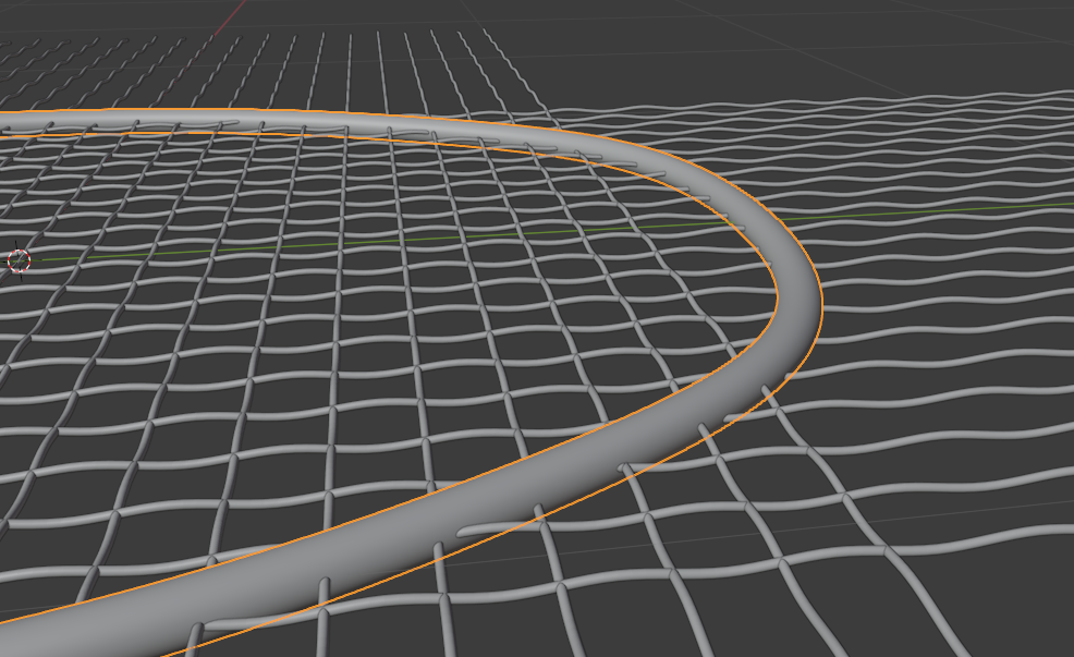
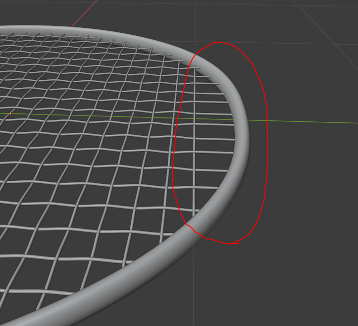
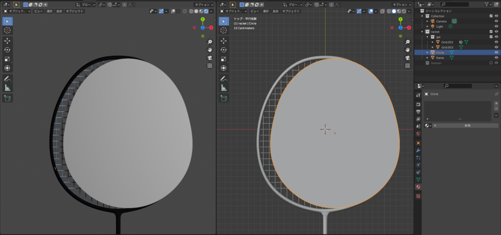
The strings near the frame extend straight in line from the contact point with the horizontal strings toward the frame due to tension, as shown in the diagram below.

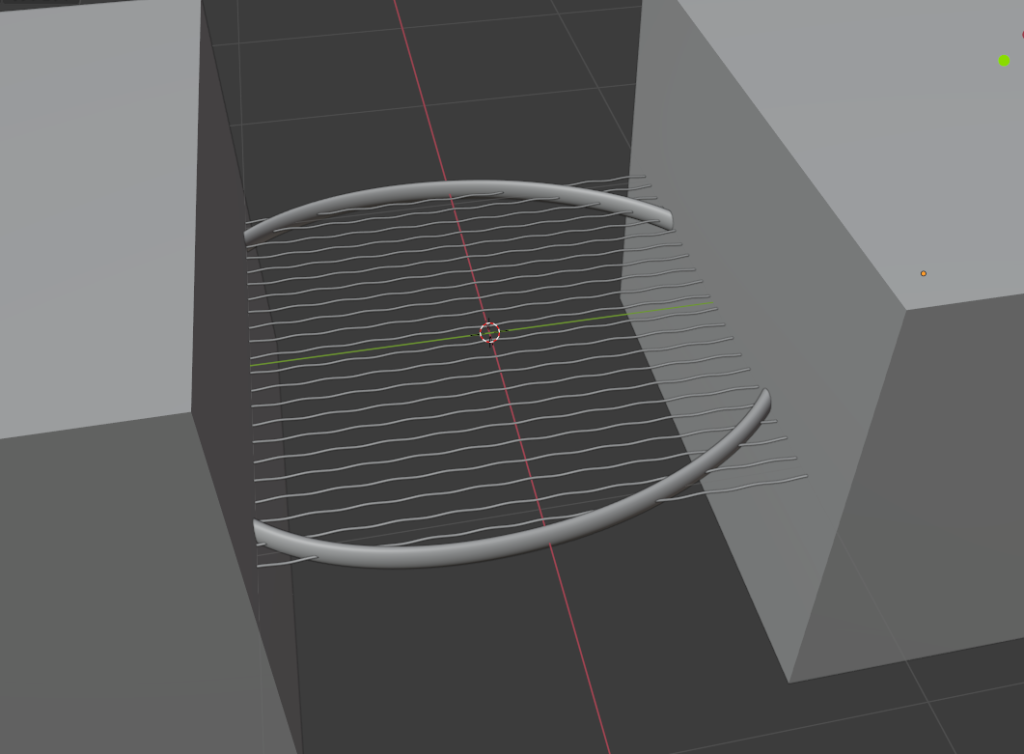
To replicate this, I used Boolean operations at the endpoint of the mesh, then extruded the strings to extend them in a straight line.
(Left: Before editing, Right: After Boolean & Extrusion, Bottom: Cube used for Boolean operation)
AD
Racket Frame
I created the frame using the following steps.
- Create a torus (referred to as the “frame").
- Adjust the size by looking at the actual racket.
- Delete half of the vertices.
- Add a mirror modifier.
- Check the “Clipping" option to ensure the two sides connect cleanly.
- Turn on proportional editing, adjust the shape, and then apply the mirror modifier.
- While still in edit mode, add a cylinder (referred to as the “shaft").
- Use scaling and other tools to shape the shaft.
- Delete the vertices at the frame’s edge where it connects to the shaft.
- Select the vertices at the frame and shaft ends and use the “Bridge Edge Loops" option from the top-left corner of the screen or press Shift + E.
- In object mode, add the “Subdivision Surface Modifier" and, if needed, add loop cuts.
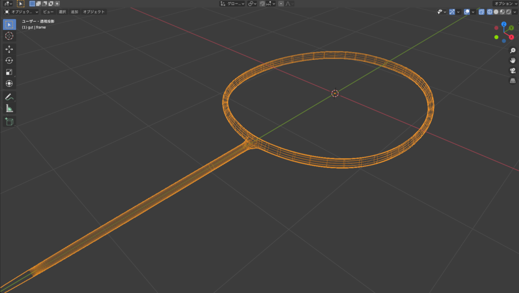
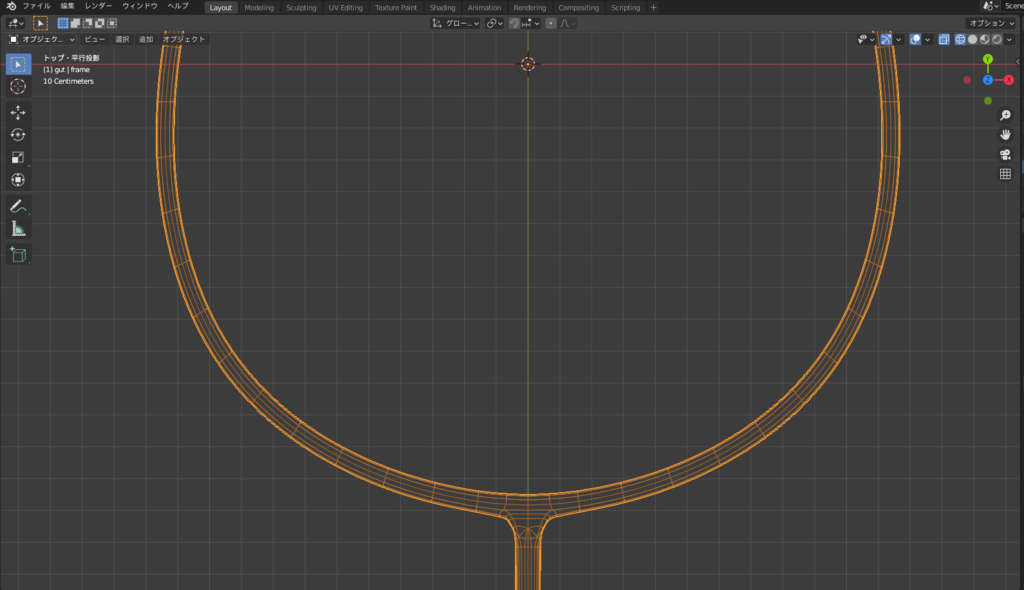
I apologize for not having the mesh during the creation process, but here is the completed mesh. 🙇💦
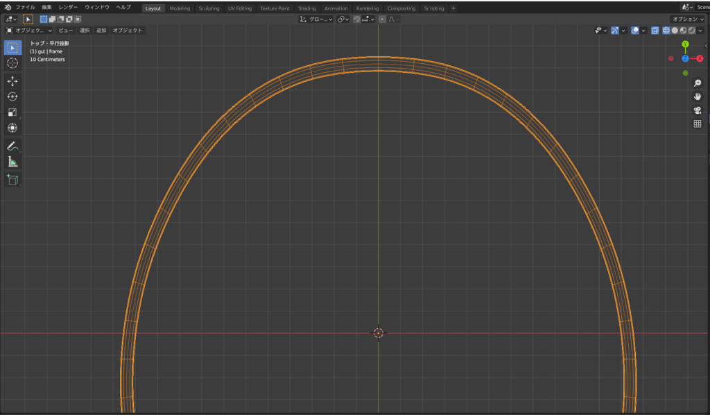
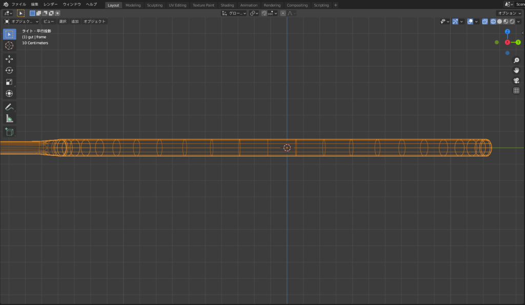
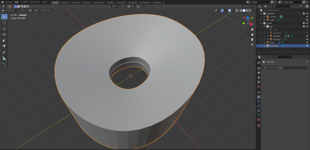
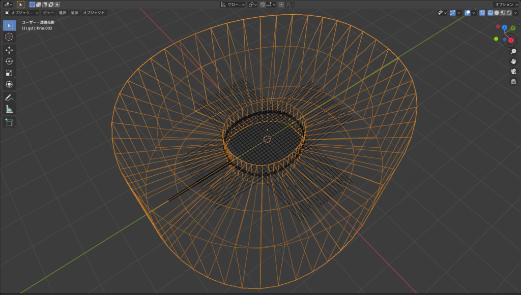
Since the strings were protruding from the frame, I followed these steps to remove them:
- In edit mode, loop select the vertices along the side of the frame (Alt + Left-click).
- Duplicate the selection with Shift + D, and then separate it into a new object with P.
- In edit mode, select the separated vertices, extrude them using E to create a cylindrical shape, then use Alt + E to “Extrude Along Normals."
- The extrusion distance should be long enough to hide the strings protruding from the frame.
- Select the strings (gut) and add a “Boolean Modifier," choosing the separated object from step 3 as the reference object.
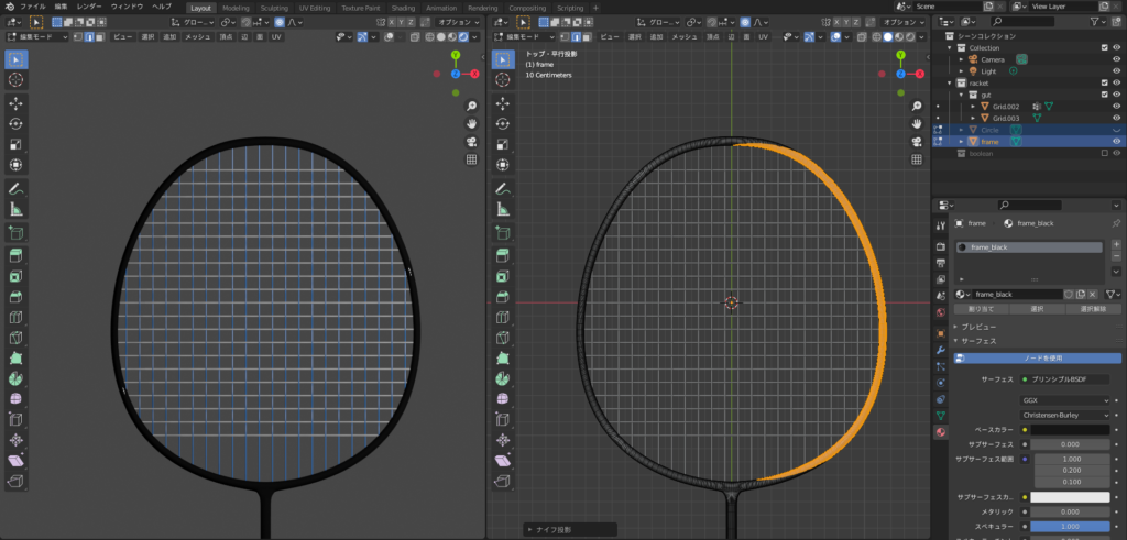
Here is how the mesh looks that I used for the boolean operation:
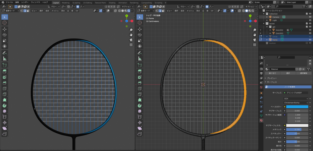
For the finishing touches, I colored the frame in black and blue.
First, I set the black material. Then, I used knife projection for range selection and added the blue material, as shown below. 😊
Shuttlecock (Feathers)シャトルコック(羽根)
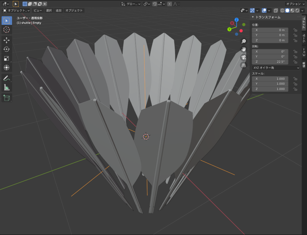
I used the “Array Modifier + Empty" technique, which I previously introduced in the article on “Police Badge (Cherry Blossom Emblem) & Koban" to create the feathers for the shuttlecock.
Shuttlecock (Feathers) Creation Steps
- Add a plane and scale it along the X-axis (S → X) to elongate it.
- Add a loop cut and divide it into 5 segments along the length direction.
- Select the vertices, then scale (S → Y) to make both ends thinner.
- Add a loop cut, then bevel it to shape the feather.
- Select the edges, then extrude (E → X) the end edges to create the feather’s point.
- Select the face and extrude the central part of the feather to add thickness.
- Add a subdivision surface modifier and use loop cuts to refine the shape.
- Add an Empty (Cross) object.
- Tilt and position the feather slightly upwards in relation to the Empty object.
- Press Ctrl + A → Apply All Transforms to reset the shape.
- Select the feather, add an Array Modifier, and set the Empty object as the target. Set the number of copies to 16.
- Select the Empty object and rotate it 22.5° around the Z-axis (360° ÷ 16).
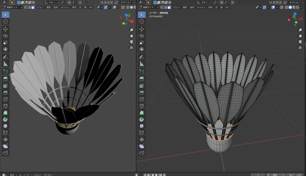
- Add a UV sphere, delete the top half of the vertices.
- Select the remaining vertices of the cut-off area, extrude them, and create the faces.
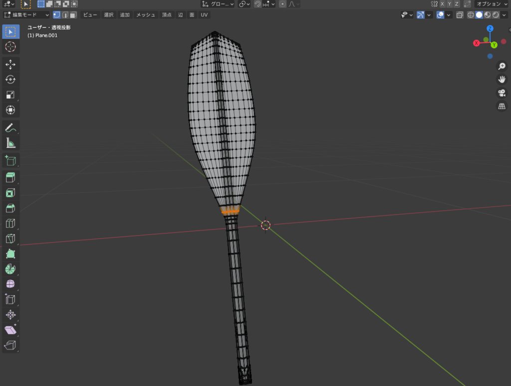
Here are the intermediate and final mesh stages. I referred to the real-life object and applied colors to complete the shuttlecock! 😊
Things I Worked On
I aimed to make it as realistic as possible by closely observing the real object to replicate the shape and color. 🧐✨
Challenges/Reflections
Connecting the racket and shaft at the joint using edge loops was tricky. It was difficult to make the transition smooth. 😅
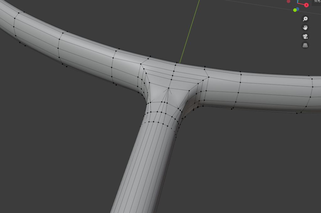
Using “LoopTools" to smooth out the mesh on the frame side and then connecting it to the shaft would definitely make the transition smoother.
AD
Conclusion
By applying Sasara Bch’s tutorial, I was able to recreate a badminton racket in Blender 😊✨
It was a moment where two completely unrelated hobbies, “Blender" and “Badminton," came together in a miraculous collaboration 😆 haha!
Reference Tutorials
Sasara Bch, Blender M01-014【Net】
Sasara Bch, Blender M01-017【Pond Ring with Array】🍩
Sasara Bch, Blender M01-066【Cherry Blossom Crest】
AD
